Automated electronic notification provides a way to easily alert the business application users of the change in the system status and to stay organized, informed and in-touch 24/7. Oracle ESS provides the ability to notify users of the status of submitted jobs, and the recipient information can be specified via the user interface 'Notification' tab for submitting job requests. Notifications will be sent upon the successful completion of a job, or when a job completes in an error or warning state.
ESS delivers the notifications to the relevant users using the Oracle SOA Suite User Messaging Service (UMS). The UMS Server orchestrates message flows and will route outbound messages from the ESS client application to the appropriate UMS driver. UMS Drivers support widely-adopted messaging protocols and can be integrated with existing infrastructures such as a corporate email servers or XMPP (Jabber) servers.
The ESS Notification post processing action is used to notify users as to the completion status of the request. The Subject and Body of these notifications are preset to standard messages so users will always get the same information - as to whether a request has succeeded or failed, regardless which job was run. Also, ESS does not force these notifications to be sent via Email - a user may configure their UMS preferences such that their default channel is SMS (or text message), Instant Messaging, etc.
There are two configuration settings that affect how ESS interacts with UMS. These are:
• NotificationServiceURL
• SAMLTokenPolicyURI
The NotificationServiceURL is of the form http://<host>:<port> and indicates the server where UMS is running. If this is not set correctly, or if the http:// prefix is missing, Notification will not succeed. The SAMLTokenPolicyURI is used if such security has been configured for the UMS server. Notification is designed to handle the case of a null SAMLTokenPolicyURI and continue accordingly in the assumption that the null value indicates no SAMLTokenPolicy is required.
These notification settings are part of the ESSAPP connections configuration. ESS specific connections.xml will contain token expressions which will get materialized with concrete data obtained from the adf-domain-config.xml at runtime. The domain wide configuration file adf-domain-config.xml will maintain all the ADF connection parameters in Metadata Services(MDS) repository, and provides a centralized way to update all connections information used in Fusion Applications.
ESS connections xml attribute values can be modified using Mbeans. The MBeans save the changes in MDS, and the values in MDS override the values in the actual connections.xml file. ESS script 'essAdfDomainConfig.sh' implemented using WLST provides command line options to modify the ESS connections.xml parameters created in the MDS repository (if there is a need to modify the UMS server url properties).
Some important points to note when submitting the job using the ESS Request Submission user interface:
1. Check User preference for the user/recipient is setup with notification
2. Make sure that submitter is specifying the username (not email address) of the recipient user that is in ldap in the UI notification tab.
3. Ensure that ESS hosting application where the job is running includes oracle.sdp.client library reference in weblogic-application.xml.
Please refer the official Oracle documentation for more details on ESS notification, UMS user preferences configuration and troubleshooting.
Thursday, July 25, 2013
Friday, June 28, 2013
Configuring Oracle SOA TLOGS JDBC Persistence Store using WLST Offline
In this post, we will look at configuring Oracle SOA to use TLog JDBC persistent stores using WLST (offline).
First, some info on TLogs. Weblogic Server (WLS) holds records of the state of in-flight transactions that are marked to be committed, in a 'TLOG' (Transaction Log) persistent store. The persistent store can either be files on a file-system or a table in database. When an instance is restarted, the TLog files are used to perform the second step of a two-phase commit on a transaction that was in progress.
So, why is this persistent-store configuration important? Configuring a WLS TLOG store to persist transaction logs to a database provides the following benefits (covered in the WLS documentation):
- Leverages replication and High Availability characteristics of the underlying database.
- Simplifies disaster recovery by allowing the easy synchronization of the state of the database and TLOGs.
- Improved Transaction Recovery service migration as the transaction logs to do not need to be migrated (copied) to a new location.
Now onto the sample WLST OFFLINE python script to see how the persistent store configuration can be accomplished. At a high level, the SOA TLOG configuration script enables JDBC Persistent Store for each Weblogic SOA managed server that belongs to
the SOA Cluster. The script was verified in a 11g SOA PS6 env and will give you a general idea on what commands need to be executed.
Friday, May 31, 2013
Oracle SOA Suite JMS Deployment Topology
Java Message Service (JMS) messaging architecture relies on a data centric approach for application integration. The Oracle Service Oriented Architecture (SOA) core infrastructure engine (or ESB) implements messaging to enable services to be integrated in a message-based paradigm – both synchronous and asynchronous styles. Hence, for those familiar or working with SOA Suite 11g, it becomes necessary to know the SOA JMS resources that are configured in Weblogic Server.
So, when it comes to understanding JMS deployment in a Weblogic environment, it helps to be aware of the major components of the WebLogic JMS Server architecture. JMS Servers act as management containers for JMS Queue and Topic destinations in JMS Modules, which contains configuration resources such as Queues, Topics, distributed Destinations and Connections Factories. These JMS module resources are grouped and targeted to Weblogic server resources such as JMS servers, server instances, or cluster by a mechanism called SubDeployment. Information on JMS modules' administered objects are placed in a JNDI namespace and are written to the file <product-module-name>--jms.xml in the config\jms subdirectory of the domain directory. The JMS module will be referenced in the domain's config.xml file as a <jms-system-resource> element.
Here is a representation of the JMS resources deployment from a standalone i.e. non-cluster SOA Suite 11g-PS6 deployment, that could be helpful in enhancing your understanding. The persistent store depicted can either be 'File' or a table in database.

Some points to remember for a successful JMS resources deployment and transparent access:
Refer the official documentation for latest and greater details on Weblogic JMS architecture.
So, when it comes to understanding JMS deployment in a Weblogic environment, it helps to be aware of the major components of the WebLogic JMS Server architecture. JMS Servers act as management containers for JMS Queue and Topic destinations in JMS Modules, which contains configuration resources such as Queues, Topics, distributed Destinations and Connections Factories. These JMS module resources are grouped and targeted to Weblogic server resources such as JMS servers, server instances, or cluster by a mechanism called SubDeployment. Information on JMS modules' administered objects are placed in a JNDI namespace and are written to the file <product-module-name>--jms.xml in the config\jms subdirectory of the domain directory. The JMS module will be referenced in the domain's config.xml file as a <jms-system-resource> element.
Here is a representation of the JMS resources deployment from a standalone i.e. non-cluster SOA Suite 11g-PS6 deployment, that could be helpful in enhancing your understanding. The persistent store depicted can either be 'File' or a table in database.

Some points to remember for a successful JMS resources deployment and transparent access:
- All JMS server names must be unique within a domain and across all inter-operating domains
- All JMS store (File or JDBC) names must be unique and have unique MBean names
- All user-defined JMS connection factories targeted to servers/clusters in a domain must have unique JNDI and MBean names
- Queue destinations can use the same name as other Queues on different JMS servers
- Topic destinations can also use the same name as other Topics on different JMS servers
Refer the official documentation for latest and greater details on Weblogic JMS architecture.
Wednesday, January 30, 2013
Oracle ESS Jobs Thread Allocation
Oracle
Enterprise Scheduler includes a Request Processor component, which represents a
single Managed Server in the Oracle Enterprise Scheduler cluster. Request Processors
process job requests, such that job execution is connected to one or more
request processors. Oracle Weblogic Server “Work Managers” helps ESS to
prioritize work and allocate the threads for job execution, through
configuration of a Work Assignment and
binding the Work Assignment to a Request Processor.
A little
background on how WebLogic Server (WLS) handles requests by assigning them execute threads. WLS uses
the concept of Work Managers to provide
applications a way to control thread utilization. Oracle WebLogic Server uses socket muxers, which read messages from
the network, bundle them into a package of work, and queue them to the Work
Manager. The Work Manager then finds a thread on which to execute the work and
makes sure the response gets back to the same socket from which the request
came. WLS uses a single thread pool, in which all types of work are executed. The
server prioritizes work based on rules you define, and run-time metrics,
including the actual time it takes to execute a request and the rate at which
requests are entering and leaving the pool.
Creating a Work Assignment is fundamental to understanding how threads are allocated to ESS job request execution and how you can limit the period during which job requests of a certain type can be processed.

Figure: Binding Work Assignments EssWA1 and EssWA2 to ESS Managed Servers
A work assignment includes two primary components that define Request Processor constraints:
- Specialization Rules: Define restrictions for job request processing on a request processor.
- Workshifts: Specify temporal windows for processing job requests and thus describe the schedule for when job requests can be processed on a request processor
Here is a simple example on how Work Assignments can be used for 4 concurrent ESS SubRequests. This assumes that all SubRequests use the same job definition and that job definition is not used for any other purpose.
- Create Schedule for appropriate time period.
- Create Workshift with 4 threads that use the Schedule.
- Create Work Assignment specialized to that job definition, and add Workshift.
- Bind Work Assignment to one server in exclusive mode.
Friday, December 28, 2012
Generating Reports using Oracle Enterprise Scheduling Services (ESS)
Let me start of by stating that Oracle ESS does not provide any in-built mechanism or feature for generating reports. Oracle Business Intelligence Publisher (BIP) is the report generation and delivery engine for Fusion Applications and ESS simply takes advantage of this.
Here is some high level information on how ESS-BIP job submission works. The best part for application developers is that, they do not have to implement the code to invoke BIP from ESS; they just need to focus on defining the ESS job definition using BIP or Java JobType and specify the report attributes. ESS invokes the BIP agent API to submit a job report request, which will be picked up by the BI Publisher report processors. BIP agent API implementation internally calls asynchronous web service to generate data and process all delivery channels for that job report request. As part of ESS-BIP job submission, request parameters like requestId, job definition, job package name etc are updated in the ApplSession, which is propagated to the BIP server. Callback to the configured ESS web service happens after BIP finishes a report job.
ESS global submission user interface 'Output' tab provides options through which an end user can specify layout templates for reports, document formats (PDF, RTF), and report destinations (email, fax, printer). Depending on the file management group (FMG) property set for the ESS job definition, the relevant post-processing action is selected for the job. Post-processing actions can also be invoked programmatically from a client using a Java or web service API.
Also, you might want to check out the BI Publisher report bursting capability, where in report will slice the data to generate multiple output files by identifying required format and delivery options during report runtime. Each output can be delivered to multiple delivery channels. ESS Central Submission UI allows developers to specify bursting or non bursting using property name 'outputCollection' with value 'Y' or 'N'. Value 'N' indicates that no further BI report post processing action should be allowed.
Note that Report output (bursting and regular BIP report) will be stored in BIP repository.
As always, please refer the official Oracle ESS/Fusion Apps Developers Guide for more details.
Tuesday, November 27, 2012
Oracle ESS FND Data Security
In the Oracle Enterprise Scheduling Services (ESS) world, the mechanism to protect job request information is data security. ESS relies on the Oracle Fusion Data Security technology to implement data security and enforce security authorization for a specific data record or a set of records. Data security provides access control within Oracle Fusion applications on the data a user can access and the actions a user can perform on that data.
An overview of the high level steps involved in securing ESS request data is shown below:

Note: ESS Request History Access Control feature depends on FND_GRANTS, and so depends on FND_SESSION (application session). The application user session is the session that Oracle Fusion Data Security expects to see. Creating a ViewObject using ESS REQUEST HISTORY table will bypass ESS data security, as it is not protected by Virtual Private Database (VPD); and therefore it is strongly discouraged to do so. Moreover, this approach will lead to inconsistent behavior with ESS data security model.
Remember to always check the official Oracle ESS documentation for latest information on this topic ...
Monday, October 29, 2012
Systems Perspective on Software Development Project Cycle
The “Cloud” has become the dominant global trend in Enterprise IT today and the big question for many businesses is how to transform their IT model or adapt cloud initiatives to align with their strategy, structure and processes. I would like to take a step back and take a systems approach to analyze the challenges in the current software development life-cycle. I think a systems model will help in learning about the dynamic complexity of IT development projects and understand the sources of resistance to design more effective system models/policies for cloud transformation strategies.
I created a causal loop diagram to understand the challenges and relationships between different variables of the IT project cycle. The intent is to include sufficient number of key variables and their relationships to represent reality.
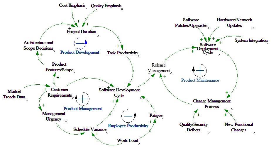
The Causal Loop Diagram shows four important loops:
1. Product Development (Balancing loop)
2. Product Management (Reinforcing loop)
3. Employee Productivity (Balancing loop)
4. Product Maintenance (Reinforcing loop)
The balancing Product Development loop illustrates that when there is an increase in customer requirements, need for scoping the existing software functionality and architectural design decisions increase as well. The reinforcing Product Management loop suggests that perturbations such as management actions can lead quickly to major changes in project schedule, prioritization and performance.
There is one key negative feedback loop - Employee Productivity. This loop reflects the assumption that if a task falls behind schedule or there is a critical customer requirement, management will direct workers to work overtime to put the task back on schedule in order to satisfy customer deadlines. The Product Maintenance loop represents the post development maintenance activities that involve deploying the software to meet customer business requirements.
Among other things, I think one of the significant advantages for software development teams will be to leverage the cloud vendor for the infrastructural related maintenance activities. Another causal loop diagram depicting the cloud IaaS/PaaS/SaaS model will reveal the finer details. Will get to it next ...
Subscribe to:
Posts (Atom)